
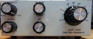
Front panel of the Oak Hills Research 100A QRP radio kit after assembly. The controls are RF and AF gain, RIT, Bandwidth, and main tuning.
The OHR 100A comes as a kit and is available from www.ohr.com, a subsidiary of Milestone Technologies. As of this writing the kit is $179.95. A ten-turn potentiometer that acts as a bandspread is available for $17.95, and a built-in keyer is available for $29.95. Although I ordered both the ten turn potentiometer and the keyer, right now I’m operating the rig “stock.” I will install both of these options in due time; in the meantime I’m getting reacquainted with my straight key.
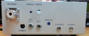
Rear panel of the Oak Hills Research 100A. The keyer option hasn’t been installed yet, so those holes are vacant. Note the unusual key connector: an RCA jack! The radio has separate connections for headphones and a speaker; attaching headphones will mute the speaker.
The radio comes with a nice case. I must say I admire the way the chassis is constructed—it has stand-offs already mounted to accept the circuit board. The front panel letters and numbers are easy to read.
Building the kit. The kit comes with a printed and drilled circuit board that’s ready to accept parts. No parts are pre-mounted. There are a few integrated circuits; each of these goes into a socket that’s soldered to the circuit board. There are quite a number of toroid coils that need to be wound by hand. Apparently some people must object to this, because (for a fee) you can get the coils pre-wound. Personally, I have no problem winding toroids, and the instructions for doing so are clear and easy to follow.
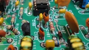
A closeup of the circuit board for the OHR 100A. D107 is a small 1N34 diode, which I mismounted the first time around. My repair wasn’t terribly neat, but it works. Note that the ICs are all in sockets; there are no surface-mount components.
Fortunately, when it was finally time to apply power, the radio actually worked! No smoke, no overheating, no fuse-blowing. I attribute this to being exceptionally careful while building it. I also attribute it to sheer dumb luck.
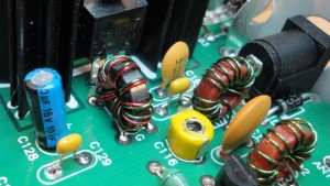
The circuit board of the OHR 100A, showing two of the transmitter toroids, one of which is bifilar (two turns on the same core). C116 (yellow) is one of the trimmer capacitors that must be adjusted.
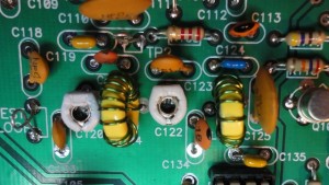
OHR 100A circuit board, showing two more trimmer capacitors that must be tweaked for best receiver performance. I had best results using a ceramic adjustment tool rather than a metal screwdriver. Note the toroids. The toroids were not hard to wind.
The first step in aligning is to spread or bunch up the windings on a toroid to get the oscillator output precisely on frequency. The setting was very sensitive to the slightest movement. You’re then instructed to put some fingernail polish or some such on the windings to hold them in place. The manual suggests letting whatever you put on the windings dry for 24 hours. I did, though I’ll admit it took some willpower because I wanted to get on with it!
The transceiver uses a sidetone generator so that you can hear what you’re transmitting. The frequency of the sidetone is independent of what frequency you might be transmitting on. I set the sidetone to 700 Hz. I then followed the instructions to align the OHR 100A’s transmit and receive frequency so that if I match the tone of an incoming signal to the 700 Hz sidetone, I would zero-beat the other signal; that is, the ham on the other end hears you transmitting exactly on his frequency. You will need your “main” transceiver to do this; in my case I used my TenTec Jupiter. Both the sidetone frequency and loudness are adjustable.
The VFO frequency is determined by a potentiometer rather than a variable capacitor. I plan to replace this with the OHR-provided ten-turn potentiometer.
I really wish there was a way to “spot” other stations. That means using the sidetone frequency as a reference so I can tune other stations to exactly match. Unfortunately, the only way to do this is to transmit briefly (one dit) so you have a reference in mind while tuning the other station. Remember, if you are not transmitting on the other station’s frequency, the other station will hear you as a tone that’s quite different from what it’s transmitting. You don’t want to be too far off.
The rig uses an RCA jack to plug in the key. An RCA jack! I’ve never, ever seen a radio that uses an RCA jack for the key! At first my key line went through several adapter cables to be able to plug in properly. Yesterday I modified my key to use a simple jumper cable from the key to the radio. I do worry though—plugging and unplugging the key really tugs the connector and I’m worried that it will eventually cause the circuit board to crack.
Marshall Emm suggested I run the RF gain control about one o’clock and the AF gain control about ten o’clock. I tried this and it works fine. The radio has no automatic gain control (AGC), so if you have the RF gain wide open, a loud signal will have you yanking off your headphones in a hurry!
The variable bandwidth control is sometimes helpful, but the bandpass skirts are anything but steep. So a loud station, even though a couple kilohertz away from your station, will still come through even with the bandwidth tuned to its narrowest point. I just put it midway and leave it there. I’m used to the “brick wall” bandpass filter on my TenTec, so this rather loose bandpass filter takes some getting used to. It reminds me of using my old Heathkit HW-16 when I was a novice. Back then any bandpass filtering was done in your head, not in the radio!
The RIT (receiver incremental tuning) control allows you to tune the receiver without changing your transmitting frequency. It’s effective and allows tuning a couple kilohertz away on either side. Be sure it’s centered (there’s a center detent) when you start a QSO, then use it to follow another station’s drift without changing your transmitting frequency. Otherwise you and the other station will chase each other all over the band!
Unlike many other QRP kits, the VFO frequency is changed using a potentiometer instead of a variable capacitor. My MFJ-9040 QRP rig uses a variable capacitor with a reduction drive, so a little indicator tells me where I am on the band. However, the OHR 100A changes from 14.000 MHz to 14.080 MHz in about three-quarters of a revolution of the knob. That means barely breathing on the knob changes the frequency by a few hundred hertz. And the pot exhibits some stiction, so fine tuning is hard. I know that this will be fixed when I install the 10:1 potentiometer, but the potentiometer reduction drive has no indicator. So, since the radio tunes across 80 kHz, I will have to remember that each turn is 8 kHz and will have to count revolutions from a band edge.
The rig gives a pretty loud click when it’s turned on, so you may want to plug in your headphones after you switch it on. There is a separate speaker jack, and the audio output is sufficient to drive a 4-inch speaker quite loudly.
There’s a bit of a thump when keying, but not objectionable. The on-the-air reports I’ve received so far indicate solid keying with no chirp or clicks.
The rig is specified to run at 13.8 VDC. My station runs on a solar-charged battery, so in the evening the voltage is down closer to 12 VDC—the rig seems to tolerate this with no problem. My straight key is a Japanese JJ-38, which I acquired back when I was a Novice, and the antenna is a Butternut HF-9V vertical.
An aside about straight keys. While operating I found many hams using slow code and straight keys. I’d always thought that a straight key made a great shelf ornament, and real CW was done with an electronic keyer and iambic paddles, but apparently the straight key is making a comeback. Key to this is an organization called the Straight Key Century Club (SKCC), and those who belong exchange their SKCC numbers. I quickly joined—my SKCC number is 13205. The SKCC folks are found on 20 meters in the neighborhood of 14.050 MHz, and I’ve found they’re quite willing to QRS (send more slowly) for me. (I do note that SKCC considers “bugs” to be straight keys, but I think pretty much everyone I’ve worked uses a straight key. Straight keys have a certain “sound” that’s unique to every operator, something called the operator’s “fist.”)
Other wishes. I wish that the power connector was an Anderson PowerPole connector. But these became popular long after the kit was designed. I created a short pigtail connector that connects to the radio and has a PowerPole connector on the other end. I also wish very much that the rig had a pilot light just so I can tell when it’s turned on! I am ambivalent about the lack of an AGC. On the one hand, you really get a good feel for the band without it, but on the other hand when really loud signals come in, my hand goes for the RF gain control. Oh, and the biggest wish of all? That my rusty CW, once a solid 18 to 20 words per minute, will recover!
Hi Dave! I’ve been an OHR100 (no A) 20m operator for twenty years, and love this radio. Some periods it’s been my only rig. Thanks for this in-depth review, it’s very helpful, particularly since I’m leaning toward building a 100A 30m. (I didn’t build my trusty old 100 20m, so am in the dark about that adventure.)
I wanted to comment about that RCA key jack. First, my OHR100 actually has a 1/4″ phone jack – how old school is that?? – so the RCA-equipped OHR is new to me. But since you said you’d never seen that before, I thought I’d mention that my “big” rig – a Tentec from the 80s – also has an RCA key jack. I imagine they all did, in that era.
Come to think of it, I may retrofit my old OHR100 with an RCA key jack too, because I’ve always had to use adapters to move keys between my two rigs and it’s annoying. (And frustrating, those times I’m away from home and can’t get on the air because an adapter didn’t get into my baggage.)
Anyway, I just thought I’d chime in. I’m a big fan of my OHR, and can only imagine that the upgraded 100A is even better.
TNX,
Rob
KB7PWJ
Thanks for the tip Dave, there is! a bag of parts labelled 30mtr band pack ,i’ve heard that in some instances if you want to change a rigs freq it’s just a case of crystals for the band you want and a couple component changes
Gary, if you haven’t started yet, note that there is a bag of parts labeled 30m bandkit. Perhaps you can talk with OHR and exchange this for the 20m bandkit. 73, Dave
I got the DD-1 and the 100A in an equipment swap ,so far i’ve built the DD1 but haven’t started the 100a the kits are very well built nice enclosures, my 100A is for 30mtrs i wonder how much work it would take besides crystals to convert it to 20mtrs?
Steve, I’m sorry to hear you’re having trouble. Frustrating! I suggest contacting http://www.ohr.com. Give them a call. I had some trouble with my kit after I wrote the review, and they were very responsive. Good luck! 73, Dave
I built this rig and the drift is much worse than what you describe. It doesn’t just happen in the first 10 minutes, but continues for 45 minutes or so during which time it’s basically impossible to have a QSO with anyone without constantly touching up the tuning.
Hi Richard, I got the keyer option but never built it. I’m still very much in a mode of rebuilding my CW skills, and all the slow code is related to the Straight Key Century Club, so I’ve been using my straight key. Even with my new Yaesu, I’m using my straight key. My current comfortable code speed is about 10 wpm, a lot less than the 20 wpm I needed to get my Extra “back in the day.” I figure the best way to raise my code speed is to simply get on the air. Good luck with your OHR 100A!
Hi Dave,
Nice review, I built mine about a year ago now in preparation of building a K2 but I found the OHR 100A so good that I left the K2 alone for a while. I have also built a frequency counter which does makes things easier. I’m so impressed I fancy getting the 3om kit as well, so I’ll have a family of OHR 100A’s!! Did you ever get the keyer option? I never I’m still using a straight key I’d be interested to know what its like? – 73’s Richard M0AUW
will be great to have an schematic diagram with signal wave forms and levels at key points in the circuits… at Tx and Rx…………
Thanks Dave. I’ll do that.
72
Hi Bal, I had the thumping problem for awhile myself, but with further adjustment, it went away. I do recommend emailing Marshall—he is patient and helpful.
Hi Dave,
After rechecking all the transmitter chain components and reorganizing toroids turn I’m getting 1,86w at 12vdc and 3,8w at 13,8vdc. I can’t get more. I have an oscilloscope to make rf measurements but there is no voltage table or something like that in the manual in order to troubleshooting. I guess i’ll have to email Marshall.
Another annoying problem I have is an audio thump every key lift. I think it must be related to power supply filtering. I can’t use the headphones more than 15minutes w/o having a headache.
Thanks Dave. I’m looking forward for your second part!
72 de EA8BVP, Bal
Bal, I don’t get a full five watts either, even with the power control turned up all the way. My MFJ-993 IntelliTuner measures 4.3 watts. It’s daytime, so my photovoltaic system is running about 13.5 volts. And the tuner isn’t really designed to measure power amounts that small. But I can still get QSOs. I really should update the post with “the rest of the story,” to discuss what happened after the rig failed and I had to send it back to get it fixed. Long story, but with a successful outcome. 73, Dave, KEØOG
Hi Dave. Thanks for your review. It’s helpful.
I have a question about power output. I’m getting
2W at 12VDC and 2,6W at 13,8VDC. I can’t get 5W
as manual says.
How much are you getting?
Thanks.
72 de EA8BVP, Bal.
Many thanks Dave for the review of your OHR 100A. I am also building this kit from Marshall Emm, and it’s also for the 20m band. Thanks for posting your experiences and photos. It’s a bit reassuring that my built-up board and my own hand-made toroids look like yours!
Just a note, I’ve also built the OHR DD-1 digital display/frequency counter that I intend to use with the 100A once completed. Both kits are first class products in my opinion, with great customer care from Marshall.
I hope to work you on the air some time, though I am still learning CW from the ground up.
73
Matt
2E0MTT, UK.